Generating NTSC signals cheaply
By Ricardo

For reasons I cannot go into details publically, I got hold of an old DVR (digital video recorder) device capable of recording some analog and even IP (up to a point) security cameras, as well as some cables, adapters and even cameras themselves. By nature, there isn’t much you can do with devices like these besides.. well, either use them as a security system, or hack the DVR into something else (it’s an embedded machine afterall).
However, I always wondered if we could generate camera signals. You see, these cameras are NTSC (yes, analog!), and that’s what the DVR expects, so I can’t just connect an IP camera to it. That said, what if we could, somehow (and cheaply!), generate a valid signal it could sync to and record it - either generated by software (aka a fake video signal), or even an IP camera being converted.
Let’s find out.
Disclaimer
As usual, I have some disclaimers for you:
-
I am no expert. I learned everything through online docs, research and picking up the wrong resistors because I can’t read their values. Lots of browser tabs were involved and way too many hours of debugging were ncessary.
-
This is for research only. For obvious reasons, all of this was done in a controlled environment (aka at home), and should not be replicated outside such spaces. Do not use this to commit crimes (you know what I’m talking about). This research is educational purposes only. If you get in trouble for doing this anywhere, it’s your own fault.
-
A tiny bit of AI was used in a learning/PoC capacity. I lack time and knowledge and AI can be useful for learning and bootstraping small PoCs. Besides that, everything else was me, including the shitty circuit and setup.
Security cameras crash course
There are quite a few protocols and types of security cameras, but the focus of this research are the ones I have at hand. These are old NTSC security cameras, meaning that they generate a valid NTSC output signal. They are so simple that you can probably use a cheap NTSC do HDMI adapter to capture them.
The DVR is responsible for capturing that video signal, converting it to digital (often H.264 or similar), and then writing it to its disk. The reason why it is called a digital video recorder is because it records the video digitally instead of in an analog manner like old security systems with their VHS tapes (good days!).
Thankfully, all of this old gear has slowly been being phased out in favor of either higher resolution cameras (which better protocols), or even IP ones talking over the network. But, as we can see here, this is still in use:
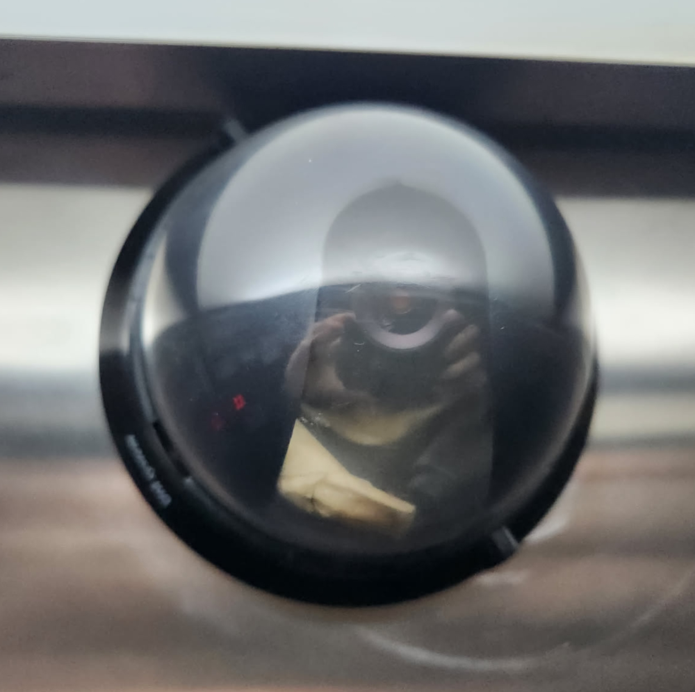
Blurry, but I know this is an analog camere (because I installed it lol)
This replacement process isn’t happening everywhere, as it takes money to replace a dozens/hundreds of cameras and devices, as well as cables in some scenarios. But at least for the ones that are being replaced, we can slowly grab some very cheap gear and have fun with it.
The NTSC standard
Disclaimer: again, not an expert.
The NTSC is an analog TV standard created back in 1941 (yes, that old). It has an incredible 29.97 fps (or 59.94 fields/sec), and was often used as a simple way to output video signal. In Brazil, ironically, we often relied on PAL-M instead, but for some reason about a decade ago most of the cheap analog security cameras were NTSC. Go figure.
Note: if you like analog video stuff, the Cathode Ray Dude has a bunch of videos talking about it!
The NTSC signal for a “frame” (not really a frame) isn’t a grid of pixels like an image, but more like a single signal that oscillates in terms of voltage. It draw top-left to bottom-right, like a normal CRT would:
That said, essentially what it represents is brightness: the higher the voltage, the brighter the pixel is. Each scanline (basically a line in the TV) is then drawn consecutively, and it takes about 63uS to do so. Between every scanline, there’s a sync pulse, which is basically a voltage so low that its brightness would be less than black. That is known as the horizontal sync, which basically is like a carriege return, but for TVs, and it takes about 4.7uS.
The signal then repeats that about 240 times, each line drawing under the previous, and that generates a field (not a frame). Once you interlace 2 fields, you get a frame, but we won’t get into those details here. That said, once you finished drawing all those lines, you need to get back to the top, and that is taken care by the vertical sync: same thing as the horizontal one, but longer (~190uS).
Note: our code will send the same field twice, and thus create a 240p image instead of 240i.
There’s also something called Vertical Blank Interval, but that’s a mess and it’s related of how CRT used to work. For the purposes of this project, all you need to know is that there will also some blanking sent after the vertical sync signals.
Finally, for the sake of clarification, there’s also something called overscan. We’ll have to deal with that in the code (partially at least), but a nice way to think about it is this: remember back in the CRT days that you had to align the image? Horizontal/vertical alignment and stretch, and you could draw outside the visible portion of the CRT? Well, that’s basically it. The image is just not the same size of the TV, and thus it draws outside the visible area. We’ll compensate by just not drawing some of the pixels outside the area captured by our DVR. That simple.
Generating a valid NTSC signal
For the sake of simplicity, we’ll start with a black-and-white signal, as it’s a bit simpler to handle. The goal here is to generate a valid NTSC signal from a Rasperry Pi Pico and capture it on the DVR. In theory, the Pico is more than capable of doing that using its PIO (programmable input/output) pins. However, to generate the right voltages, we’ll need some small circuit for that:

SVG is fun, but I also suck at drawing circuits!
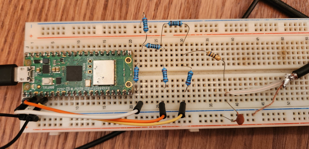
I didn’t have a 75ohm resistor so I used the closest one I had lying around.
With that circuit, the Pico pins, which can normally output only 0 or 3.3V, will be able to generate a valid NTSC signal, which is basically 0V for sync, ~0.3V for black, ~1V for white, and shades of gray between 0.3V and 1V. That circuit is a R-2R ladder, and is a very simple way of converting the digital output from the Pico into the analog one we need. Basically GP0 will add a little voltage, GP1 a bit more (2x) and GP2 will add a ton more (4x), and we can then output binary to GP0/1/2 and get the desired voltage as the output.
Now, to generate the correct signal, we need to configure the Pico to do so. The main CPU is not ideal for this, and thus we use the PIO for that. the whole program for the PIO is simply a OUT PINS, 3. It literally just grabs whatever is sent to it and outputs in the first 3 GPIO pins. That simple, in a loop, forever. To know what to output, we push things into a FIFO that is read by the PIO using DMA, and we’ll write that in our normal code whenever necessary (in our demo it will be static so it will be written during setup).
Fun fact: the CPU won’t be involved in the process. The PIO is fully independent so we’ll just run the main CPU into an infinite loop. Crazy, right?
The code below is the one responsible for this madness:
/*
 * Disclaimer: partially generated by AI, rewritten by me. Expect shitty code.
 */

#include <Arduino.h>
#include "hardware/pio.h"
#include "hardware/dma.h"
#include "hardware/clocks.h"

// Do not touch. It's just madness and a bunch of crazy stuff from NTSC.

// NOTE: on the SAMPLE_RATE, if you get jitter/bending on the image, this is because your system clock is not diving well with this value, so you can adjust it. Go figure.
static const uint32_t SAMPLE_RATE = 12500000u;
static const int LINE_SAMPLES = 794;
static const int SYNC_N = 59, FP_N = 19, BP_N = 59;
static const int ACTIVE_N = LINE_SAMPLES - SYNC_N - FP_N - BP_N;
static const int TOTAL_LINES = 262, ACTIVE_LINES = 240;
static const int VBLANK_LINES = TOTAL_LINES - ACTIVE_LINES;
static const int FIELD_SAMPLES = LINE_SAMPLES * TOTAL_LINES;

// The constants used for code simplicity, so we know what value is what.
// 000 = Sync, 010 = Black, 111 = White. (why not 001? because the signal is too low and gets misread as sync)
static const uint8_t CODE_SYNC = 0, CODE_BLACK = 2, CODE_WHITE = 7;

// This is our buffer. Anything in fieldw will be output.
static const int SAMPLES_PER_WORD = 10;
static const int FIELD_WORDS = (FIELD_SAMPLES + SAMPLES_PER_WORD - 1) / SAMPLES_PER_WORD;
static uint32_t fieldw[FIELD_WORDS] __attribute__((aligned(4)));

static int g_sample = 0;

// -- Bunch of magic stuff starts here --
static inline void pushSample(uint8_t code) {
  int w = g_sample / SAMPLES_PER_WORD;
  int slot = g_sample % SAMPLES_PER_WORD;
  // place 3 bits at slot*3; autopull shifts RIGHT so first sample = lowest bits
  fieldw[w] |= ((uint32_t)(code & 0x7)) << (slot * 3);
  g_sample++;
}

static void emitLine(const uint8_t* active /*NULL=blank*/) {
  for (int n = 0; n < FP_N;   n++) pushSample(CODE_BLACK);
  for (int n = 0; n < SYNC_N; n++) pushSample(CODE_SYNC);
  for (int n = 0; n < BP_N;   n++) pushSample(CODE_BLACK);
  for (int n = 0; n < ACTIVE_N; n++) pushSample(active ? active[n] : CODE_BLACK);
}

static void emitVsyncLine() {
  for (int n = 0; n < LINE_SAMPLES - FP_N; n++) pushSample(CODE_SYNC);
  for (int n = 0; n < FP_N; n++) pushSample(CODE_BLACK);
}

// -- More magic shit! --
static const uint16_t prog_instr[] = { 0x6003 }; // OUT PINS,3
static const struct pio_program prog = { prog_instr, 1, -1 };

static PIO pio = pio0;
static int sm = 0, dma_chan, dma_ctrl;
static uint32_t* fieldw_ptr = fieldw;

static void setupPioDma() {
  uint off = pio_add_program(pio, &prog);
  for (int g = 0; g < 3; g++) pio_gpio_init(pio, g);
  pio_sm_set_consecutive_pindirs(pio, sm, 0, 3, true);

  pio_sm_config c = pio_get_default_sm_config();
  sm_config_set_wrap(&c, off, off);
  sm_config_set_out_pins(&c, 0, 3);
  // shift RIGHT, autopull enabled, threshold 30 bits -> refills after 10 samples
  sm_config_set_out_shift(&c, true, true, 30);
  sm_config_set_fifo_join(&c, PIO_FIFO_JOIN_TX);
  sm_config_set_clkdiv(&c, (float)clock_get_hz(clk_sys) / (float)SAMPLE_RATE);
  pio_sm_init(pio, sm, off, &c);
  pio_sm_set_enabled(pio, sm, true);

  dma_chan = dma_claim_unused_channel(true);
  dma_ctrl = dma_claim_unused_channel(true);

  dma_channel_config dc = dma_channel_get_default_config(dma_chan);
  channel_config_set_transfer_data_size(&dc, DMA_SIZE_32);   // 32-bit words now
  channel_config_set_read_increment(&dc, true);
  channel_config_set_write_increment(&dc, false);
  channel_config_set_dreq(&dc, pio_get_dreq(pio, sm, true));
  channel_config_set_chain_to(&dc, dma_ctrl);
  dma_channel_configure(dma_chan, &dc, &pio->txf[sm], fieldw, FIELD_WORDS, false);

  dma_channel_config cc = dma_channel_get_default_config(dma_ctrl);
  channel_config_set_transfer_data_size(&cc, DMA_SIZE_32);
  channel_config_set_read_increment(&cc, false);
  channel_config_set_write_increment(&cc, false);
  fieldw_ptr = fieldw;
  dma_channel_configure(dma_ctrl, &cc,
      &dma_hw->ch[dma_chan].al3_read_addr_trig, &fieldw_ptr, 1, false);

  dma_channel_start(dma_chan);
}

// NOTE: buildField is shown below.
void setup() { buildField(); setupPioDma(); }
void loop()  { delay(1000); }
Simple, right? lol I won’t even begin to pretend I understand the full code above. I get the general idea of it, specially with the PIO stuff as I played with that in the previous SNES hacking saga, but the DMA setup was done by AI. Originally it didn’t exist but it caused some issues so we had to add it. Oh well. That said, this doesn’t change much between experiments, so I don’t really care about it. The part I reaaaaaally want to talk about is the generation of the field (“frame”), so I saved that for last:
static void buildField() {
  // Clear it all.
  for (int i = 0; i < FIELD_WORDS; i++) fieldw[i] = 0;
  g_sample = 0;

  // Send the VSYNC lines. Remember what I said about the vertical sync pulses? This is it.
  int vsync_lines = 3;
  for (int y = 0; y < vsync_lines; y++) {
    emitVsyncLine();
  }

  // Send some blank lines before the image. This is necessary, it's part of the VBI.
  int blank_lines = 15;
  for (int y = 0; y < blank_lines; y++) {
    emitLine(nullptr);
  }

  // For each line...
  for (int y = 0; y < ACTIVE_LINES; y++) {
    uint8_t row[ACTIVE_N];

    // For each column...
    for (int x = 0; x < ACTIVE_N; x++) {
      int border = 1;
      int overscan_top = 0;
      int overscan_left = 12;
      int overscan_right = 2;
      int overscan_bottom = 1;

      // Do not draw on the overscan area.
      if (y < overscan_top || y >= ACTIVE_LINES - overscan_bottom || x < overscan_left || x > ACTIVE_N - overscan_right) {
        continue;
      }

      // This will basically generate a pattern of white and black 4x4 squares.
      int cell = 4;
      int cx = x / cell;
      int cy = y / cell;
      row[x] = ((cx + cy) & 1) ? CODE_WHITE : CODE_BLACK;
    }

    // Send the row into the FIFO.
    emitLine(row);
  }

  // Add blank lines at the bottom to complete the NTSC lines (VIB still).
  int bottom_blank = (TOTAL_LINES - vsync_lines - blank_lines - ACTIVE_LINES);
  for (int y = 0; y < bottom_blank; y++) {
    emitLine(nullptr);
  }
}
The code itself isn’t too complex and it’s pretty straight forward once you get to the core of it: you have a X and Y position, and you can paint it however the hell you want. The question is: does the DVR see that? Well well well, it definitely does!
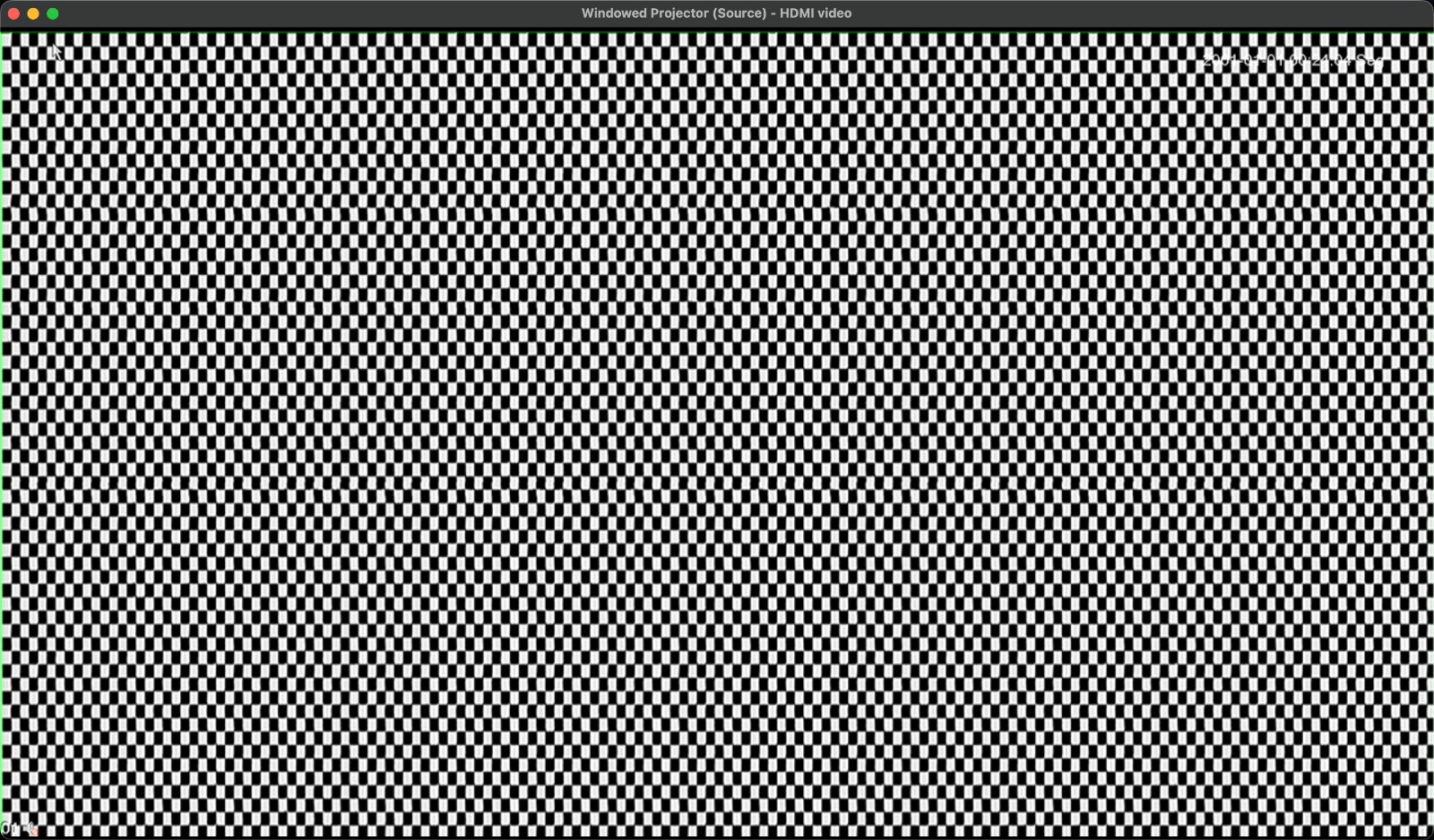
OBS HDMI capture of the DVR
Injecting a custom image
So now let’s say you want to inject a custom image. This can be a static image of any kind, as long as we can transmit it to the Pico and then make it load into its buffer. Since we probably don’t want to have the buffer overwriten while the PIO is fetching it, we’ll need two buffers: one currently being drawn, and the other being written to. Basically a double-buffering technique, just like we did previous on the PS2.
Because of that, all of our functions will have to receive which field are they going to work with: the “live field” or the “receiving field”:
static uint32_t fieldA[FIELD_WORDS] __attribute__((aligned(4)));
static uint32_t fieldB[FIELD_WORDS] __attribute__((aligned(4)));
static volatile uint32_t* liveField = fieldA;   // what DMA loops
static uint32_t* recvField = fieldB;            // free buffer we may write
To make sure we switch properly, we implement a DMA IRQ that will be triggered by an interrupt on the PIO. This is essentially a way of executing code on the main CPU once the PIO finishes reading the whole buffer. It’s ugly, I barely understand it, but it sure works:
static void __isr dmaIrqHandler() {
  if (dma_hw->ints0 & (1u << dma_chan)) {
    dma_hw->ints0 = (1u << dma_chan); // ACK
    fieldRestarts++;

    if (swapPending) {
      // Swap buffers
      uint32_t* newLive = recvField;
      recvField = (uint32_t*)liveField;
      liveField = newLive;
      dma_src   = newLive;

     // mark swap complete
      swapPending = false;
    }
  }
}

static void setupPioDma() {
  // (... normal PIO and DMA setup from before ...)

  dma_channel_set_irq0_enabled(dma_chan, true);
  irq_set_exclusive_handler(DMA_IRQ_0, dmaIrqHandler);
  irq_set_enabled(DMA_IRQ_0, true);
}
The swapPending is set by whoever receives the new field on the main CPU. That will be handled by the code getting it over wifi:
static void presentFrame() {
  uint32_t before = fieldRestarts;

  // mark swap pending
  swapPending = true;

  // hold until swap complete on the IRQ handler
  while (swapPending) { /* spin; could yield */ }
  (void)before;
}
And with that, all that is left is the actual image receiving code. Obviously the image will be prepared and converted locally before sending it to the Pico, as we’re already low on memory anyway. I won’t go over the wifi setup code as that is pretty straighforward, but here’s the actual main CPU loop receiving the image:
void loop() {
  WiFiClient cl = server.available();
  if (!cl) { delay(2); return; }

  Serial.println("client connected");

  // Keep the connection open and accept a stream of frames.
  while (cl.connected()) {
    // Header size: 4 bytes. It contains the length of the image to receive.
    uint8_t hdr[4];
    if (!readExact(cl, hdr, 4)) break;

    // Grab the length and check it.
    uint32_t len = (uint32_t)hdr[0] | ((uint32_t)hdr[1]<<8) |
                   ((uint32_t)hdr[2]<<16) | ((uint32_t)hdr[3]<<24);
    if (len != (uint32_t)FIELD_WORDS * 4) {
      Serial.print("bad len "); Serial.println(len);
      break;
    }

    // Receive the image on the receiving field (either A or B, whatever is not live at the moment).
    if (!readExact(cl, (uint8_t*)recvField, len)) break;

    // Mark swap pending. Once swap is complete, carry on.
    presentFrame();

    Serial.println("frame OK");
  }

  cl.stop();
  Serial.println("client closed");
}
Now add a bunch of other small code changes that were needed to make this work properly (basically pass buffers around everywhere), add some glitter and alcohol, et voilà, you got a working wifi receiver that will dumb whatever you send to it as an image.
But you need to get the image and send it. Honestly at this point I just copy-pasted the C code into an AI and asked it to generate a simple Python script that will send the appropriate image to the Pico. Yeah I was lazy, don’t judge me. It ain’t pretty, but anything that handles and converts images will be ugly. I’ll spare you the code for now, you don’t deserve the hell of going through AI code - trust me.
That said, I want to send the following image to the Pico and output it to the DVR. The image below is colored, so B/W convertion will mess it up, but that’s ok:

And a single command later:
$ uv run image.py --ip 172.16.9.9 --port 5005 hacktheplanet.jpeg
sent hacktheplanet.jpeg (81.3 KB)
done
And for the sake of just having fun, here’s what happens when you inject a video into it:
Amaze amaze amaze!
What can we do with it?
Well, not a lot, unless you reaaaaally want to spend time dealing with the analog circuitry necessary to deal with this. There are some interesting limitations too in using a Pico to generate the signal:
-
Color space: we are using basically less than 3 bits to represent colors (or shades of gray in this case). This obviously won’t be sufficient to represent an actual image from a place, as it will “corrupt”/“damage” the image, but it’s good enough as a proof of concept. In theory, if we increased this to 6 bits instead of 3 (by adding more IO pins), this should solve the problem, but we’d also eat a lot more memory.
-
Pretty much all NTSC cameras in the field nowadays output colored images. I had a few cameras internally break in the past and constantly output b/w images only (stuck in night vision mode, I guess?), but in general they transmit color. However, adding colors here, at least as far as research indicates, would be a lot more complex, as we would need 1) more voltage levels (aka more IO pins), 2) deal with a signal that is a lot more complex and sensitive to sync issues, and finally 3) the sample clock must locked to 3.58 MHz subcarrier, which is a mess to deal with.
That said, there’s one really cool use for this: convert an IP camera into an analog one. Sure, it will be shitty, introduce a lot of image quality loss, lack of audio and it will be slow as hell, but, in theory, you could use a (more powerful) device to convert the IP camera image into a valid field and send it to the Pico. It is the shittiest but coolest (and probably cheapest?!) IP->NTSC camera converter you could build, and in a pinch this could actually let you slowly migrate technologies.
Note: except most analog DVRs also accept IP cameras because they are just dumb Linux machines lol
Ah, and since most likely you’ll want access to the shitty code, here it is:

Regardless, stay tuned, I already have some very dumb ideas for this. Maybe we could even try to replicate those classic heist movie scenes where they switch the camera feed with a static image, huh? 😈