Having fun with the SNES
By Ricardo
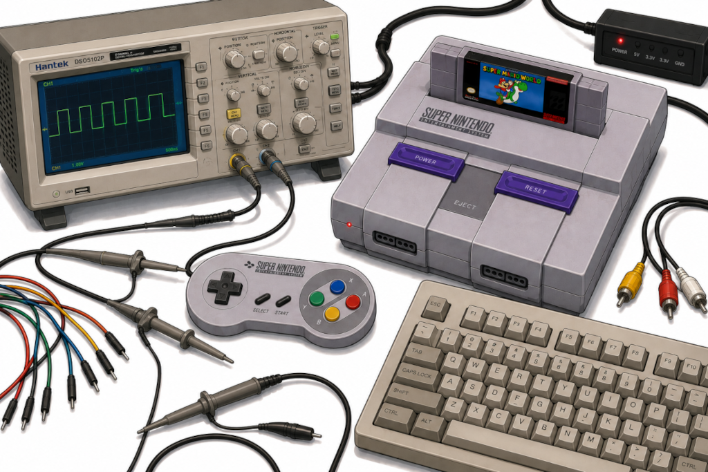
I have a very old, yellow and crusty Super Nintendo not really being used at the moment. I could be playing games, sure, but where’s the fun in that? It was stored in a box for many years, and now I’ve decided to have some fun with it - some weird fun.
Just like the previous saga of the PlayStation 2, I enjoy spending more time hacking, messing with and sometimes plain simple abusing consoles to run my own code instead of actually gaming. Plus, I always wanted to mess with the SNES anyway, so why the hell not? :)
Disclaimer
Let me get some things through right away:
-
I am no expert in the Super Nintendo. Everything you see here was done based off trial-and-error and some documentation I found online. If you try to reproduce this and your console breaks, it’s on you. You have been warned.
-
All testing was done in an emulator because my console is currently non-functional. I tried to repair it (and got super close!), but the video output is now fully dead and it might need a new S-RGB video encoder chip. I’ll send it for repair eventually. The final setup I came up with was a Raspberry Pi running Retroarch that I can spin up with SSH and the HDMI output of it being captured to my Mac. For the SNES controller USB adapter, I used some very old and crusty one I’ve built myself a decade ago using some Arduino and a very hacked bit-banged USB. It works (barely).
-
Finally, as a disclaimer, yes, unfortunately some of the code was generated by AI (Claude Code). I know, I know, it sucks. Nobody wants some AI slop, especially me. That said, it is a useful tool for experimenting and doing some quick and (extremely) dirty proof of concepts, as well as evaluating some ideas on a platform I lack a lot of knowledge about. This ain’t production code and this is for fun only, so hold your stones for those who push AI code into production, not for the ones who use it as a tool to try and learn something new, or even to make something weird like this project.
Ok, now that we have aligned our expectations, let’s talk money fun projects!
The Super Nintendo Entertainment System
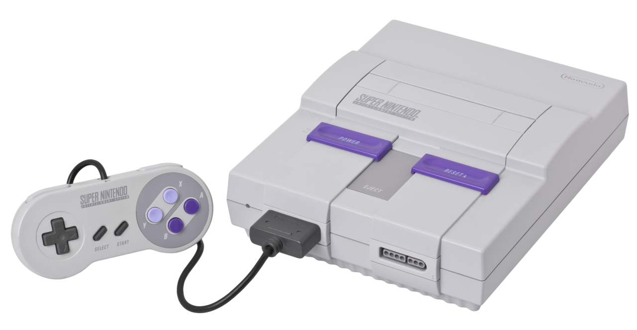
The SNES is a console released by Nintendo back in 1990. It is a 16-bit console with a Ricoh 5A22 CPU running at incredible 3.58MHz and amazing 128KB of RAM (+64KB for video, +64KB for audio). That’s basically all we need to know about it since we won’t be using much of it for gaming anyway.
The fact it uses a non-standard CPU complicates things though. It requires us to use a specific compiler that can target such hardware. Contrary to our previous PS2 shenanigans, there is no GCC for this, not even LLVM (as far as I remember), which limits a bit the kind of code we can write to it. That shouldn’t matter though as most of the code we’ll run will have to be simple anyway due to the limited amount of resources.
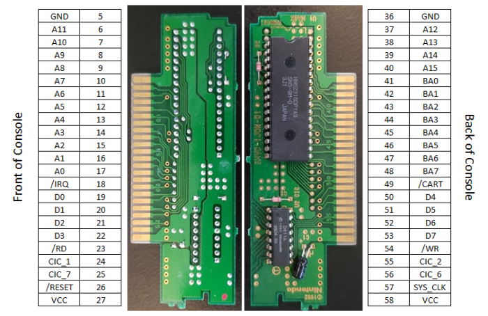
Getting data into it
The SNES has basically one main mechanism to load data into: the cartridge slot. However, messing up with that seems extremely complicated and dangerous, and also not very practical. I mean, look at this thing:
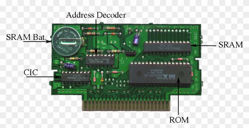
That said, there are a few ways to go here. One approach is to inject data through the ROM itself, either by using a super fast microcontroller or just an FPGA (like this). This way you could basically reply to something different every time you fetch data from it, sort of a retro version of this. The downside of this approach is that I don’t have the required circuits to do this, plus timing of ROM ICs is a pain in the butt to deal with.
Another crazy-ass idea is to replace the SRAM IC from a cartridge with a dual-port one, which, in theory, would allow us and the console to read and write to a single, shared memory straight in the cartridge.
This would obviously require modifying one, which I’m not really willing to do, but also is a bit dangerous in general. However, in theory, this could allow us to have some sort of mechanism where the SNES could write data out for us to read, and we could write data in for the console to read, creating a communication channel. Timing and wiring would be super annoying, and also things would get very nasty to debug. That said, in theory, this could be done.
Fun fact: ChatGPT, when questioned about the technical details of this, suggested I modify an Everdrive cartridge for this. It has no concept of how much these things cost over here. Yikes.
There’s also always the EXT connector, located at the bottom of the console:
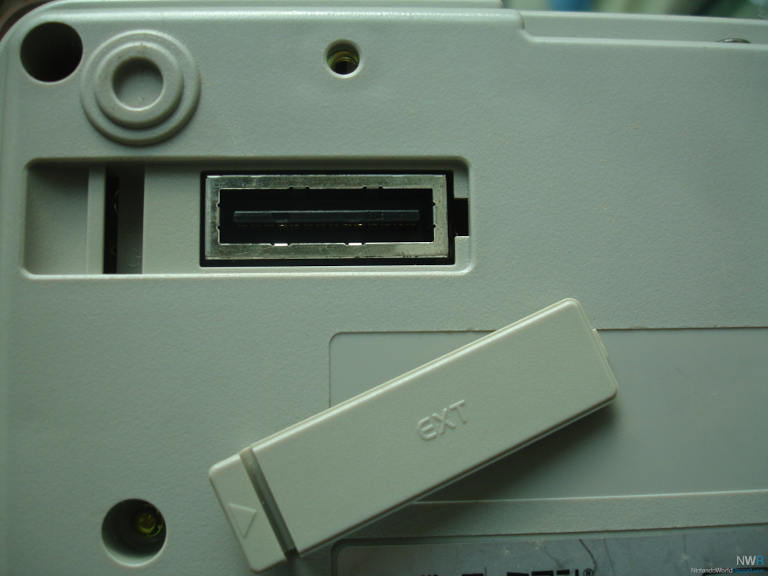
The Expansion Slot, as it is called, was originally designed for expanding the console’s capabilities with compatible devices. As far as I can find, only a few devices were made to connect to such port, and it’s mostly Japanese-market stuff, like the Satellaview (a satellite modem for the SNES?!) and a bike (wtf?).
That said, the pinout indicates this is a very low level port, often interfacing directly with some CPU pins:
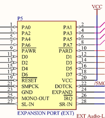
This goes back to our problem: it’s a bit too complex for what we want. It’s the same as modifying/injecting/hacking the cartridge slot for me, with the strong downside of trying to find a compatible connector for that thing.
After lots of thinking and some Coke Zero, I remembered something I saw over a decade ago on YouTube: the TASBot. If you are not aware of it, please watch this crazy video from 2014:
There’s a very good explanation of it by Ars Technica, but the TL;DR of it is that the code was glitched through very precise controller inputs.
Controller inputs.
If the controller port can be used to input data (duh), we can use it to inject whatever we want… right?
The weird keyboard idea
Noone ever said you need to connect a real gamepad to the controller port: as long as whatever you connect to it can reply to its protocol, we’re good. Speaking of protocol, look at this beauty:
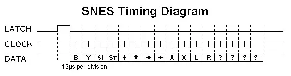
This is a very simple protocol: every X amount of time (60Hz in the real console if I recall correctly?), the console will send a LATCH signal for the gamepad to push all of its data into a shift register. Then, at every CLOCK falling edge, it will read the state of the button. Repeat that 16 times (yes), and you are done! That simple.
Yes, the controller has 16 bits we could use for sending data. The only reason why you won’t see me use and abuse those extra bits and limit some of my button presses to “realistic” ones is because I’m using an emulator to test all of this as my actual console is not working at the time of these experiments. But, in the future, we could 100% use all the bits as we wanted.
With that said, I kept wondering if I could somehow connect a normal USB keyboard to it (through an adapter, obviously). You know, just for fun.
USB to SNES
For dealing with the timing of the SNES controller protocol, I need something fast. Of all devices I have available, I ended up opting for a Raspberry Pi Pico, also known as RP2040. It has programmable input/output (PIO) state machines, which can be configured to deal with the whole protocol for us while the main CPU deals with other stuff. The Pico has 2 PIOs which we can use, and we’ll use both: one for USB (TinyUSB), for reading the keyboard keys, and the other for the SNES controller protocol.
Since I’m not planning on using external peripherals for gaming, but for other crazy ideas, I designed a very simple protocol to send data:
- No button presses when there’s no data.
- D-Pad as a data type indicator + 8 bits (A, B, X, Y, Select, Start, Shoulder Left, Shoulder Right) for whatever data I want to send.
My initial experiment is to inject data through a keyboard: I type something on a keyboard and it shows on the screen. For that, I picked the down as the data type. So here’s how it looks like for the 8 bits of data:
0x01to0x7F: ASCII. Standard controls included:\b(0x08),\t(0x09),\n(0x0A),\r(0x0D), Esc (0x1B), Space (0x20), etc.0x80to0xFF: non-ASCII keys. Arrows, Home/End/PgUp/PgDn, F1–F12, Ins/Del, etc.
If you want to check the whole table, a full list of keystrokes is provided.
The above scheme was AI generated. I changed a few rules, but in general it’s stable enough.
Now, to transmit all of this to the SNES, we need to program the PIO state machine. Since TinyUSB is using PIO0, we’ll use PIO1 for it. The code is actually pretty simple, and this is how it looks like:
  const uint16_t prog[] = {
    pio_encode_pull(false, true),                      // 0: pull block
    pio_encode_wait_gpio(true,  SNES_LATCH_PIN),       // 1: wait LATCH rise
    pio_encode_wait_gpio(false, SNES_LATCH_PIN),       // 2: wait LATCH fall
    pio_encode_set(pio_y, 15),                         // 3: y = 15 (16 iter)
    pio_encode_jmp_pin(0),                             // 4: <clk_loop> LATCH? restart
    pio_encode_out(pio_pins, 1),                       // 5: emit bit N
    pio_encode_wait_gpio(false, SNES_CLOCK_PIN),       // 6: wait CLK fall
    pio_encode_wait_gpio(true,  SNES_CLOCK_PIN),       // 7: wait CLK rise
    pio_encode_jmp_y_dec(4),                           // 8: loop back to 4
    pio_encode_set(pio_pins, 1),                       // 9: DATA = HIGH idle
  };
It’s a very simple program, as you can see:
- Wait for the
LATCHto go up and down. - Repeat 16 times:
- Emit one bit
- Wait for the
CLOCKto go down and then up again (completing the read) - Reset
DATAto high
That’s it. There’s a FIFO to communicate between the main CPU and the PIO, but I’m not going into the details of this because it gets out of the scope. Plus, this is one of the moments where I just delegated to AI to generate chunks of the code so I wouldn’t have to do lots of manual coding.
This is how the circuit looks like:
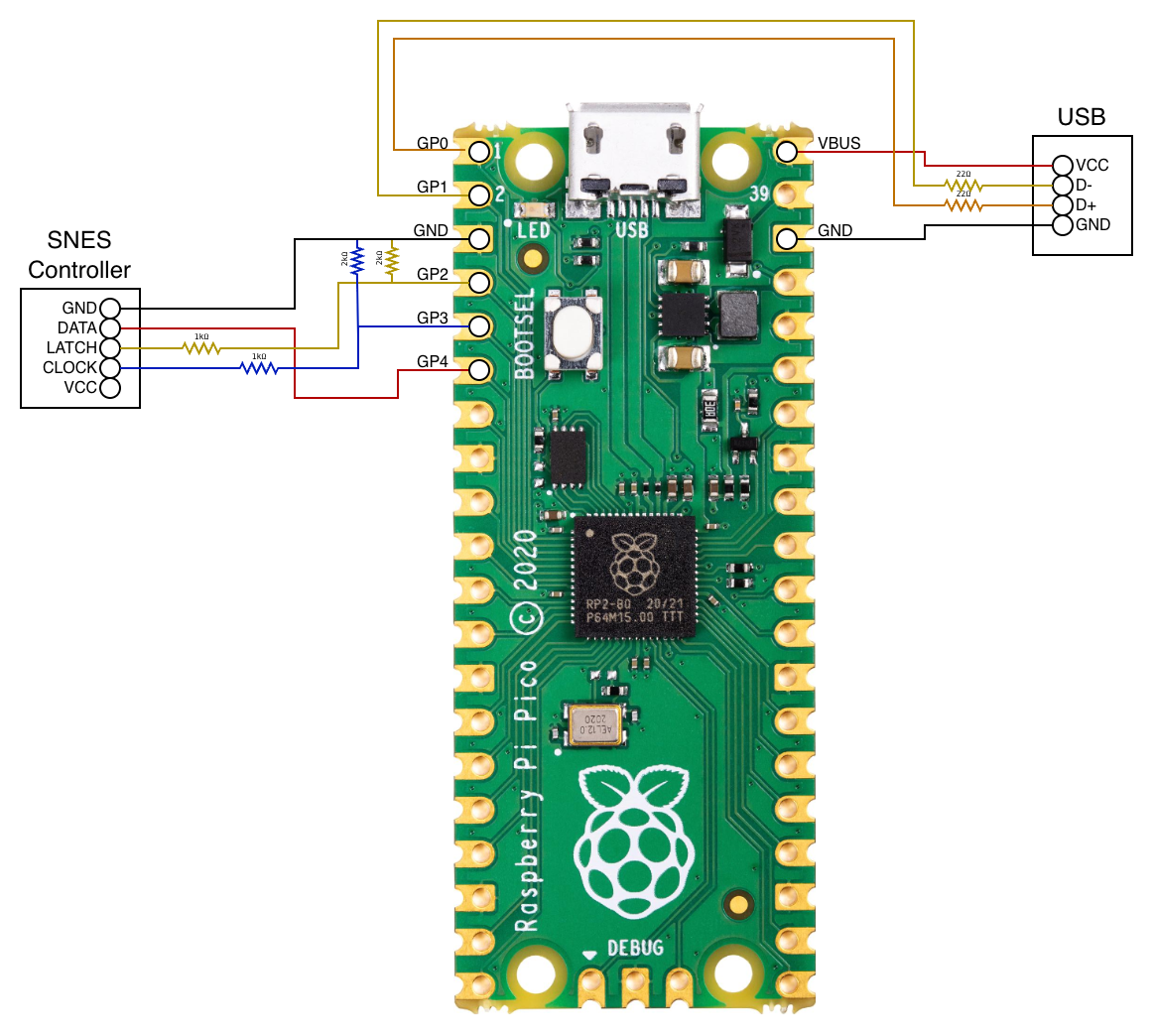
On the SNES side of things, we use some resistors to lower the 5V a bit so that it doesn’t fry the GPIO pins on the Pico. For the Pico to SNES (DATA pin), we don’t care about it, as the 3.3V from the Pico is fine for the SNES to read. Finally, the USB also needed some resistors for the sake of it. Nothing crazy.
I even made a small board:
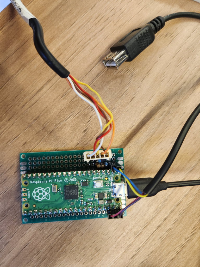
Almost looks like I know what I’m doing
With everything wired up, this is how things look like once you start typing:
Yes, it was supposed to be down, but the adapter I made (!) has a software bug where down and up are reversed. Oopsie!
The ROM
For a ROM, we need something that reads our protocol and decodes it. I basically want to output the data in a simple way so that we can actually show text on the screen. Nothing crazy.
I asked AI to generate some code for me, and it generated the following:
int main(void) {
    // Console + background setup (boilerplate from hello_world example).
    consoleSetTextMapPtr(0x6800);
    consoleSetTextGfxPtr(0x3000);
    consoleSetTextOffset(0x0100);
    consoleInitText(0, 16 * 2, &tilfont, &palfont);

    bgSetGfxPtr(0, 0x2000);
    bgSetMapPtr(0, 0x6800, SC_32x32);

    setMode(BG_MODE1, 0);
    bgSetDisable(1);
    bgSetDisable(2);

    consoleDrawText(2, 1, "USB KBD -> SNES PORT");
    consoleDrawText(2, 2, "TYPE TO ECHO BELOW:");

    clear_screen();
    setScreenOn();

    unsigned short prev_pad = 0;

    while (1) {
        unsigned short pad = padsCurrent(0);

        // Rising edge of DOWN = a fresh data frame from the bridge.
        if ((pad & KEY_DOWN) && !(prev_pad & KEY_DOWN)) {
            unsigned char byte = decode_byte(pad);

            if (byte >= 0x20 && byte < 0x7F) {
                // Printable ASCII (space through '~'). Render it.
                put_char((char) byte);
            }
            // Other bytes (control codes, extended keys) are ignored for now.
        }

        prev_pad = pad;
        WaitForVBlank();
    }
    return 0;
}
I don’t like using AI to generate code like this, but I ran out of power (literally, a transformer blew up outside!) and needed some dumb code fast. Plus this is just a proof of concept anyway.
That said, it sure works:
It works!
Ok, great: we have a keyboard, a way to input things in, and it all works. Now we need to make this… useful somehow.
Getting back to the basics
One super weird idea is to have a BASIC interpreter in the SNES. This is, to be honest, a very dumb idea, but let’s do it anyway! We need a very simple, portable and lightweight BASIC interpreter, and I ended up finding this one online:

Great! Now we just need to learn how to port this for the SNES. Let’s pick the Basic 1.0 from it (this). Navigating through the code (and going back and forth with AI for some questions), we came up with an interesting approach:
-
Reuse most of the Arduino code. This is because we can treat the SNES as a microcontroller and not care about POSIX stuff and standard libraries that won’t be available to us anyway. The following code, extracted from
basic.cshows us a clear reason why we behave as an Arduino:#ifndef ARDUINO typedef unsigned char uint8_t; #define PROGMEM #include <stdio.h> #include <stdlib.h> // (...) -
Then we inject our own hardware things in a specific
hardware-snes.hfile with our hardware rules. Most of them can be no-ops, but serial in and out must be specified:void serialwrite(char c) { snes_putchar(c); } char serialread(void) { while (!keyboard_available()) { WaitForVBlank(); keyboard_poll(); } return (char) keyboard_read(); }The keyboard code is provided by us, obviously. -
Then just code whatever is necessary and disable whatever is unnecessary. For example, we have no float support (do we? I didn’t check!), so we can disable that. We also don’t need to have separate memory for program and data, as the SNES has a flat memory layout. We don’t have GPIO too, so we can drop that. And the list goes on…
This approach is quite interesting because, just like our previous hack with the PS2, we basically reuse whatever we can, and modify whatever we need. You know, code reusability and other shit we have to care about.
That said, the question is: does it even work? Building it requires the usage of the pvsneslib (which I relied a lot on for this project) and a valid compiler - in this case, the Tiny C Compiler (tcc), modified for the 65816 CPU. I didn’t bother doing all of this manually though: a simple Makefile just like any demo will be sufficient to trigger the expected behavior.
And sure enough, as you can see below, once built, it works just… fine?
Success! 🎉
Exfiltrating data
Sometimes you need to get data out from the SNES. You have the screen for this, but sometimes you need to do that programmatically, without the user being able to see it. For example, let’s say you calculated the state of something and you need to expose this now: how? There are only a few ways of doing this without exploring the EXT port and cartridge slot hacks.
The pretty solution
One solution would be exploiting the LATCH. In theory, we could manually control the LATCH through register $4016. We could then create sort of a protocol based on the timing of signal changes, such as X microseconds being high and Y microseconds being low, or even based on the rising/falling edges of them. The CLOCK signal, however, is also triggered by the same register, but on read operations, so we should be able to do this in a bidirectional manner somehow?
Quick note: the register
$4016will trigger latch on both controller ports. This is not a major concern, but we do need to keep it in mind when reading the other port.
For example, we could map data output as follows:
- Block start/end: high for 12us
- High: high for 36us
- Low: high for 24us
Note: we can probably improve this by having a different end of packet to avoid confusion on the state machine. That’s fine, this is just an example. We could reencode things in so many different ways…
So if we wanted to encode 97 (ASCII a), we would need to send 01100001 as following:

I did this in Excel lol
Once the packet has been received, we just decode and have fun with it. Obviously the transmit speed would be super low, but I don’t care about that (the SNES itself is pretty slow hehe).
And, finally, to trigger data receiving we can just read register $4016 instead, which will trigger the CLOCK signal to go through for the 16 bits. We could modify the Pico PIO code to not rely on the LATCH signal anymore, and only handle the CLOCK ones. Since we would be manually controlling both signals, this should work just fine (in theory).
This is, however, very theoretical and has never been tested in a real console. In fact, you do need a real console for this, because the emulator will have a lot of layers impacting and dropping data here, unfortunately. Also the emulator won’t translate those signals into my USB adapter, because the adapter itself triggers the LATCH and CLOCK signals to read the controller inputs and then converts them to USB. So a lot is lost in the translation, unfortunately.
But we’ll get there… eventually.
The ugly solution
Now, let’s talk about a very ugly way of transmitting data: the audio output. Assuming our code does not need to emit sounds of any kind, we can use the audio processor to encode and transmit data in any way or shape we want. Since the data is kinda 8bit, we can use the analog pin of the Pico to decode the transmitted data.
This is super ugly. Like, extremely ugly. Not only that the audio processor is a whole CPU by itself, it’s a pain in the ass to control. But, in theory, this could be possible, right? This is essentially what a modem does on one end: it modulates data into something - and in this case, audio!
So here’s the plan: let’s encode bits in a 15ms window, being bit 0 encoded as 5ms high followed by 10ms low, and bit 1 the inverse of it, 10ms high and 5ms low. Like this:

Then, to make sure we have proper data in/out, AI suggested us to have a frame structure. I… kinda agree with it, but for testing purposes I also wrote a version of the code without it. That said, here’s how the frame looks like:
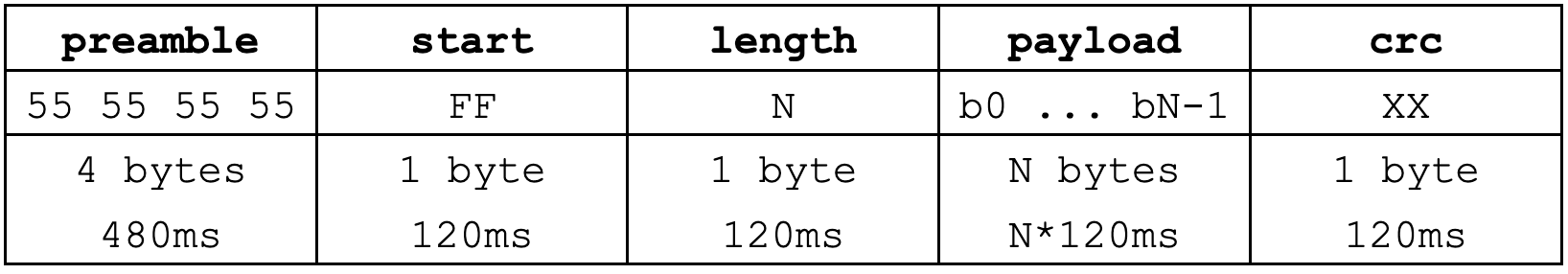
Here’s the explanation of each field:
preamble: alternating bits help the decoder hard-sync after any noise / silence before the framestart: unambiguous0xFF(= 8 consecutive 1-bits, would never occur inside4*0x55preamble)length: payload byte count,0..255(decoder buffer ceiling)crc: polynomial0x07(CRC-8/CCITT), computed over (length byte || payload). Detects single-bit flips and most short bursts from misdecoded pulses.
Total wire time would be (5 + N + 1) * 120 ms = 720 + 120*N ms. So outputting a single byte would cost us 0.84s, and a payload of 64 bytes would be over 8 seconds. Definitely not fast, but fun to listen to (I promise).
The actual frame sending code is pretty simple:
void audio_send_frame(const unsigned char *payload, unsigned char len)
{
    unsigned char crc_buf[256];  /* len byte + up to 255 payload bytes */
    unsigned short i;
    unsigned char crc;

    /* CRC covers (length byte || payload) */
    crc_buf[0] = len;
    for (i = 0; i < len; i++) crc_buf[i + 1] = payload[i];
    crc = crc8(crc_buf, (unsigned char)(len + 1));

    /* Preamble (4 bytes of $55 = alternating bits, helps the decoder lock) */
    audio_send_byte(0x55);
    audio_send_byte(0x55);
    audio_send_byte(0x55);
    audio_send_byte(0x55);

    /* Start marker */
    audio_send_byte(0xFF);

    /* Length + payload + CRC */
    audio_send_byte(len);
    for (i = 0; i < len; i++) audio_send_byte(payload[i]);
    audio_send_byte(crc);
}
Note from your narrator: I won’t even bother to share the code for the audio sending algorithm, the
audio_send_bytefunction. This part was fully written by AI because I suck at understanding the audio processor of the SNES. I’ll eventually study and learn it (because I have other crazy plans for it!), but, honestly, it’s a complex beast. There are multiple parts involved, including one that only takes care of the transmission bit, with a lot of DSP initialization code. It’s… very complex, to say the least. We’ll get there one day, don’t worry.
Cool. We have that in C. But I want to have that in BASIC because fuck it, we’re already deep into this hell, might as well have a beer with the devil, right? So I’ve created 2 BASIC functions to use that:
OUT n: encapsulateninto the frame and transmit it. That simple.ncan be a string or a number, whatever rocks your boat.OUTR n: transmit the raw data fornin a frameless fashion.ncan be the same as above, and this is used for debugging purposes and for the cool scope shots coming up next.
Testing it, the OUTR 170 (10101010 in binary) outputs the following audio signal:
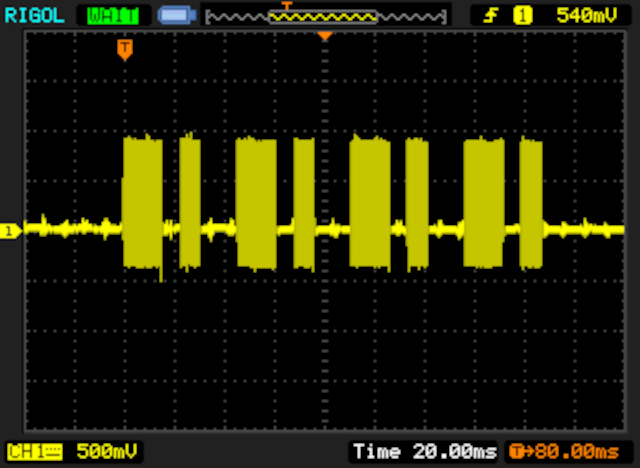
This is the audio capture from the sound card btw.
In this image you can clearly see the bits themselves, actually:
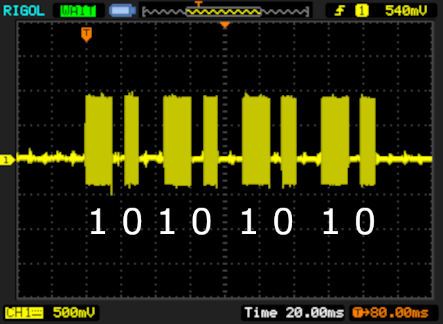
Told you it was pretty obvious! (yes I suck at aligning things ok)
However, if you zoom in, you can see the fact that it is actually an AC signal (well, duh, it’s sound!):
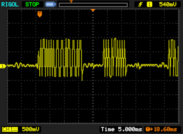
That isn’t a problem though. Even though we’re transmitting digital data, we’re doing it over sound, so this is technically correct. If the line was just high/low like a TTL signal, there wouldn’t be sound (unless it was super fast because PWM but that’s a whole different discussion). Our circuit (soon) will bias it and should be able to handle it anyway because the ADC is capable of processing such things. Plus, we care more about the duration of such “waves”, so this should be fine.
That said, here’s how a whole frame looks like (OUT 170):
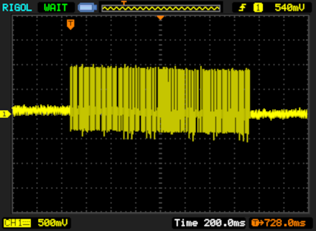
Told you it was big!
Great, this should allow us to output some data from the SNES! But now we need to decode that data. We can do it in software, but I’d much rather have the Pico do it for me, since we already have an ADC pin at our disposal anyway. For that, we need to wire a few things up first:
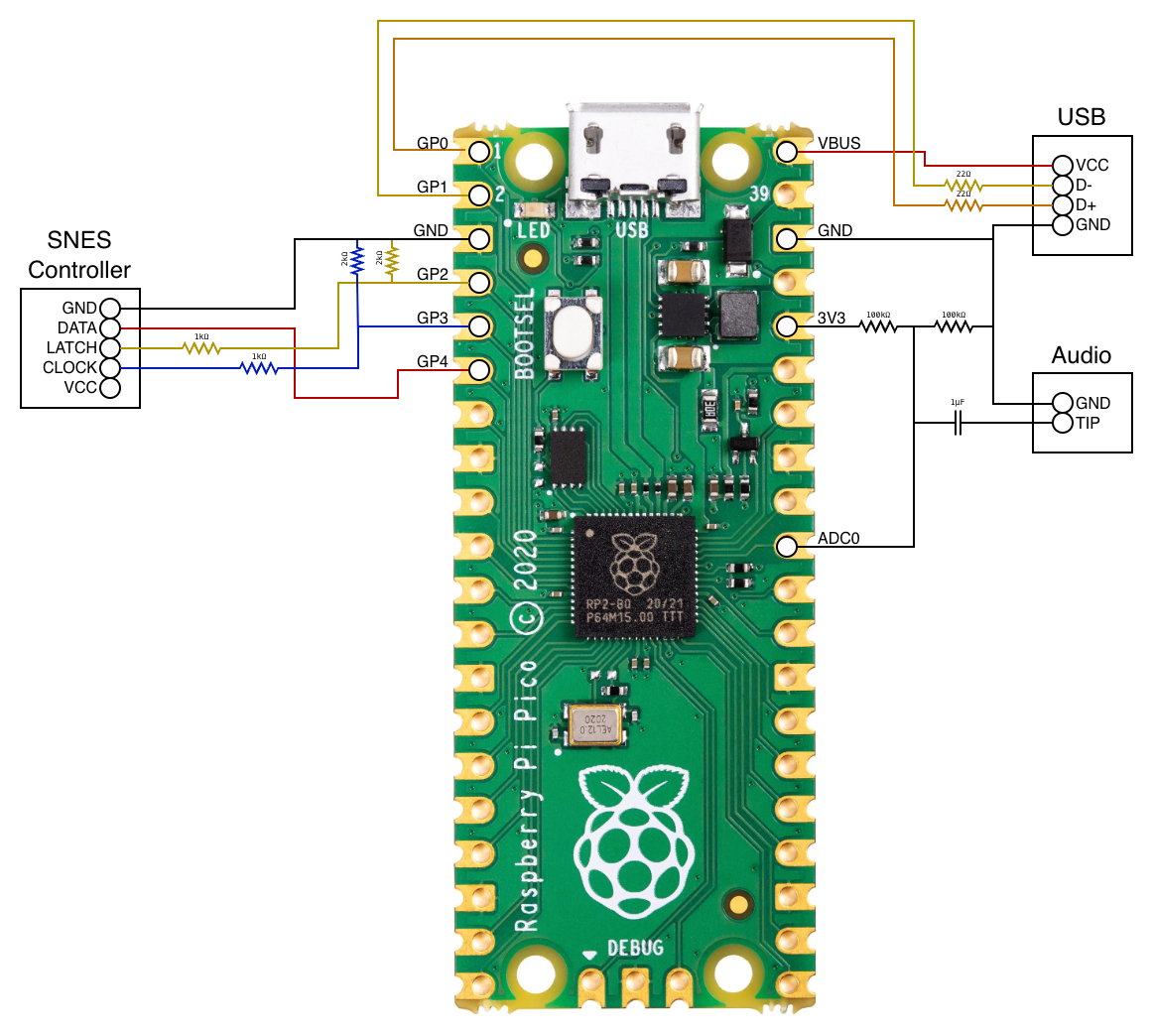
After that, this is how the signal looks like:
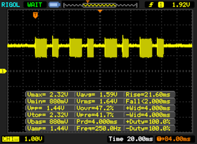
With measurements for extra fun!
Still pretty “easy” to decode, but with this bias it might be easier on the ADC to handle it (or so I was told). With the help of AI, some very crappy and buggy decoding code was written for it. AI ain’t made for this kind of crappy hacking, that’s for sure. Anyway, the code ain’t anything too wild, it’s basically counting the time between pulses above/below certain thresholds and interpreting that as bits. Once a frame has been decoded, it outputs it to serial.
The biggest question is: does it even work? And how does it sound? Well, grab some popcorn because you are in for a fun (short) video! (tip: watch with sound!)
To be honest, even I didn’t expect this to work so well, even more on an emulator. Fuck yeah!
What’s next?
Well, I have a bunch of ideas. The major limitation right now is the lack of a working console. But I plan on exploring the whole 16 bits of the controller port to make sure we can get a faster transfer rate, which will allow us to do a lot of weird stuff. This means I may also try the pretty solution for data output instead of audio (although that has a smaller cool factor). I may also consider looking into custom cartridges, which gives me a whole new level of possibilities in terms of injecting and exfiltrating data, albeit with the risk of frying the CPU if I make a mistake in the wiring…
That said, the next plan on my list is to improve the communication process by speeding things up (currently it’s super slow), and then have this as a layer that can be used for software development. This means we can do all sorts of things, including communication with external devices. The Pico, for example, could work as a modem of some sort for network access, if we so desire. Who knows, maybe we can get actual multi-console multiplayer on the SNES… the possibilities are endless!
Stay tuned!